Design in CAD
Nested steel tubes with matching holes and a clamping bolt: how one bolt holds every spring steel tine in place and carries the support wheel.
I drew this in Fusion 360.
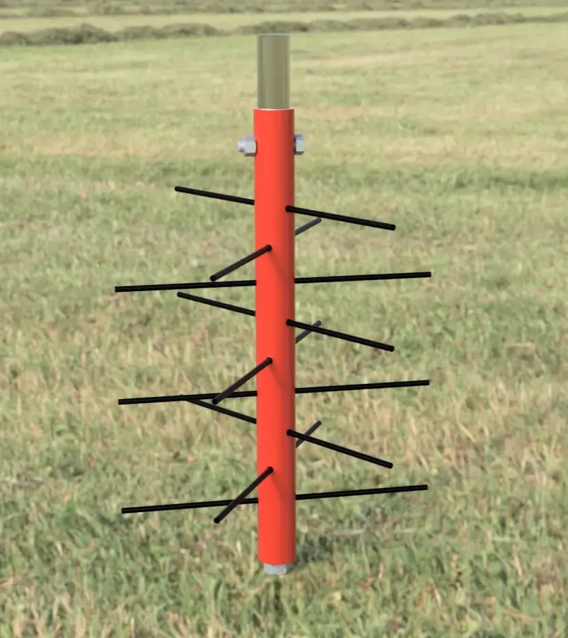
Each side of the tiller gets one unit that replaces the tilling tines. It slides over the axle shaft and is held by a cross bolt, just like the original tines.
Dimensions
These are the drawings for one unit, and you need two.
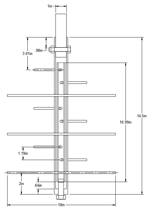
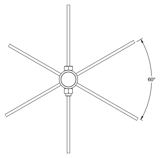
The drawings leave the stock sizes out to stay readable, so here they are along with what the dimensions work out to:
| Part | Size |
|---|---|
| Outer tube | 1 1/4 in OD x 0.12 in wall (1.01 in ID) DOM steel, 14.5 in long |
| Inner tube | 3/4 in OD x 0.109 in wall DOM steel, about 11 in long |
| Tines | 9 per unit, 3/16 in music wire, 10 in long |
| Tine holes | 7/32 in, through both tubes |
| Hole spacing | 1 3/16 in center to center, stepping 60 degrees around the tube each time |
| First hole | 3.01 in from the shaft end of the outer tube, to its center |
| Last hole | 2 in from the far end of the outer tube, to its center |
The .66 in at the far end of the drawing is space for the clamp bolt. The inner tube only moves a small amount to clamp the tines, not that whole distance.
Both units are identical.
How it goes together
This cutaway render shows how it goes together:
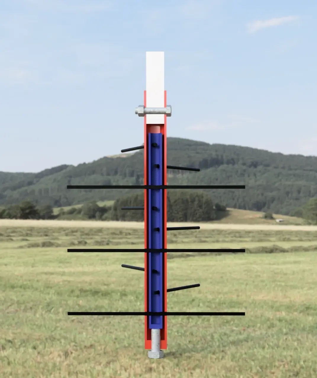
- Axle shaft (white): 1 in round, slides into the outer tube and is held by the tiller’s original 3/8 in cross bolt. The .98 in on the drawing matches the hole in my tiller’s shaft, so check yours.
- Outer tube (red): 1 1/4 in OD steel tube, with an end cap and a welded nut on the far end.
- Inner tube (blue): 3/4 in OD steel tube, with its own end cap.
- Tines (black): 3/16 in music wire, which is spring steel, running through matching holes in both tubes.
- Bolt in the far end: 1/2 in, threads through the nut and presses on the inner tube. It also carries the support wheel.
Clamping the tines
The holes in the two tubes line up, so the wires slide through. Tightening the far-end bolt then pushes the inner tube along inside the outer one, which puts tension on every tine and holds it in place. One bolt does all of them.
That only works if the holes line up very closely. If one hole is off, its neighbors take the strain, so the build has to keep the two tubes aligned while they’re drilled.
Support wheels
These tines are counter-rotating, so left to themselves they want to dig in. A 10 in solid rubber wheel on the end of each unit stops that.